Real & Virtual Images (Oxford AQA IGCSE Physics)
Revision Note

Author
Ann HowellExpertise
Physics Content Creator
Images
Images produced by lenses can be one of two types:
A real image
A virtual image
The size of an image produced by either lens depends on the distance between the object and the lens
Real images
A real image is defined as:
An image is formed when light rays from an object converge to meet each other and can be projected onto a screen
A real image is one produced by the convergence of light towards a focus
Real images are always inverted (upside down compared to the object)
Real images can be projected onto pieces of paper or screens
An example of a real image is the image formed on a cinema screen
A real image formed by a projector

Virtual images
A virtual image is defined as:
An image is formed when the light rays from an object do not meet but appear to meet behind the lens and cannot be projected onto a screen
A virtual image is formed by the divergence of light away from a point
Virtual images are always upright
Virtual images cannot be projected onto a piece of paper or a screen
An example of a virtual image is a person's reflection in a mirror
A virtual image formed by a mirror

Ray Diagrams
Ray diagrams can be used to show the images formed by lenses
Whether an image is real or virtual is determined by:
The distance between the object and lens compared to the focal length
The size of the image (magnified, diminished or same size) is also determined by:
The distance between the object and lens compared to the focal length
Whether the image is upright or inverted is determined by:
Whether the image is real or virtual
Upright images are virtual and inverted images are real
Convex lenses and real images
Object placed between f and 2f
The diagram below shows the image formed when the object is placed at a distance between one focal length (f) and two focal lengths (2f) from the lens
Real, enlarged and inverted image formed by a converging lens
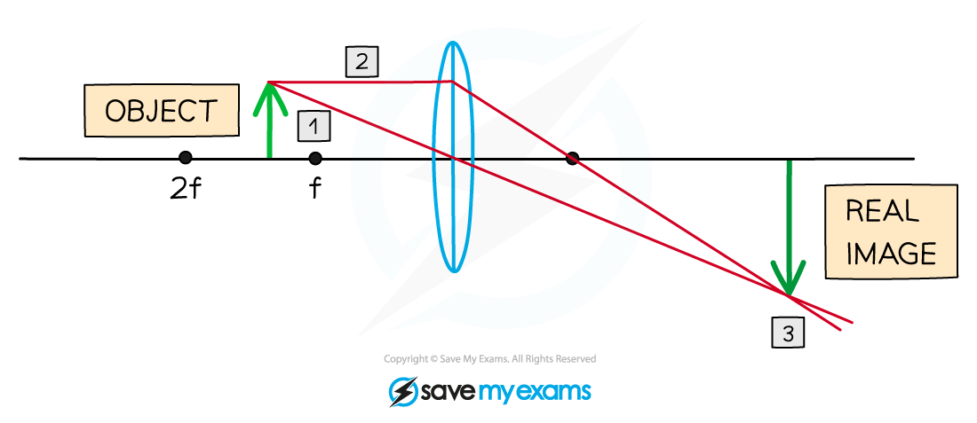
In this case, the image is:
Real
Enlarged
Inverted
Object placed further than 2f
The following diagram shows what happens when the object is more distanced – further than twice the focal length (2f) from the lens
Real, diminished and inverted image formed by a converging lens
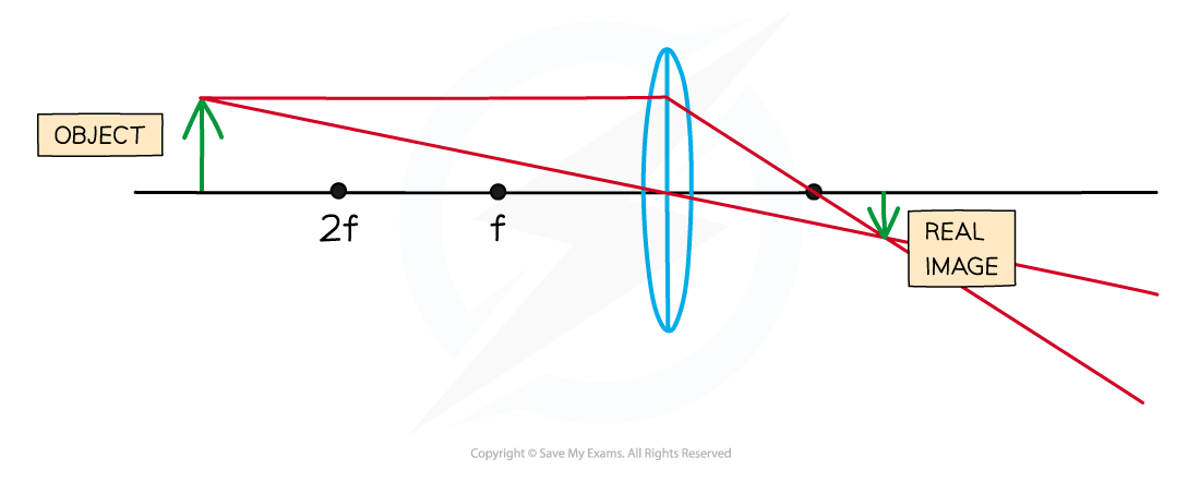
In this case, the image is:
Real
Diminished (smaller)
Inverted
Object placed at exactly 2f
If the object is placed at exactly twice the focal length (2f) from the lens
Real, same size and inverted image formed by a converging lens

In this case, the image is:
Real
Same size as the object
Inverted
To draw an accurate ray diagram of real images formed using convex lenses:
Start by drawing a ray going from the top of the object through the centre of the lens. This ray will continue to travel in a straight line
Next draw a ray going from the top of the object, travelling parallel to the axis of the lens. When this ray emerges from the lens it will travel directly towards the principal focus
The image is found at the point where the above two rays meet
Convex lenses and virtual images
Virtual, magnified and upright image formed by a converging lens

In this case, the image is:
Virtual: the light rays appear to meet when produced backwards
Magnified: the image is larger than the object
Upright: the image is formed on the same side of the principal axis
To draw an accurate ray diagram of virtual images formed using convex lenses:
Start by drawing a ray going from the top of the object through the centre of the lens. This ray will continue to travel in a straight line
Draw a dashed line continuing this ray upwards
Next draw a ray going from the top of the object, travelling parallel to the axis to the lens. When this ray emerges from the lens it will travel directly through the principal focus f
Also, draw a dashed line continuing this ray upwards
The image is the line drawn from the axis to the point where the two dashed lines meet
Concave lenses and virtual images
Virtual, diminished and upright image formed by a diverging lens

In this case, the image is:
Virtual: the light rays appear to meet when produced backwards
Diminished: the image is smaller than the object
Upright: the image is formed on the same side of the principal axis
Concave lenses can also be used to form virtual images
If an object is placed further from the lens than the principal focus f then a diverging lens ray diagram will be drawn in the following way:
Start by drawing a ray going from the top of the object through the centre of the lens. This ray will continue to travel in a straight line
Next draw a ray going from the top of the object, travelling parallel to the axis to the lens. When this ray emerges from the lens it will travel directly upwards away from the axis
Draw a dashed line continuing this ray downwards to the principal focus, f
The image is the line drawn from the axis to the point where the above two rays meet
Comparing converging and diverging lenses
The image produced by a converging lens can be either real or virtual
This means the image can be inverted (real) or upright (virtual)
The image produced by a diverging lens is always virtual
This means the image will always be upright
Worked Example
An object is placed outside the principal focus of a diverging lens.

Complete the ray diagram by drawing where the image of this object will be seen.
Answer:

Step 1: Draw a line from the top of the object through the middle of the lens
The top of the image lies somewhere along this line
Step 2: Draw a line from the principal focus through the top of the lens
The dashed line shows the continuation of the upwards arrow
The top of the image is where the two lines cross
Exam Tip
The best way to remember these ray diagrams is to draw them and see the results for yourself. Remember to always use a ruler or a straight edge in the exam to produce the most accurate drawings and gain full marks.

You've read 0 of your 0 free revision notes
Get unlimited access
to absolutely everything:
- Downloadable PDFs
- Unlimited Revision Notes
- Topic Questions
- Past Papers
- Model Answers
- Videos (Maths and Science)
Did this page help you?