Series Circuits (Oxford AQA IGCSE Physics)
Revision Note

Author
Ann HowellExpertise
Physics Content Creator
Series Circuit
There are two ways of joining electrical components:
In series
In parallel
Some circuits include both series and parallel parts
For components connected in series:
the combined resistance is the sum of the resistance of each component
the current is the same in each component
the total potential difference of the power supply is shared between the components
The combined voltage of several sources in series is their sum
Current in series
In a series circuit, the current is the same value at any point
So all components have the same current
The number of electrons per second that pass through one part of the circuit is the same number that passes through any other part
Current is the same

The amount of current flowing in a series circuit depends on:
The voltage of the power source
The total resistance of the components
This is Ohm's law, but applied to the circuit as a whole
Increasing the voltage of the power source drives more current around the circuit
So, decreasing the voltage of the power source reduces the current
Increasing the number of components in the circuit increases the total resistance
Hence less current flows through the circuit
Increasing the voltage and number of components

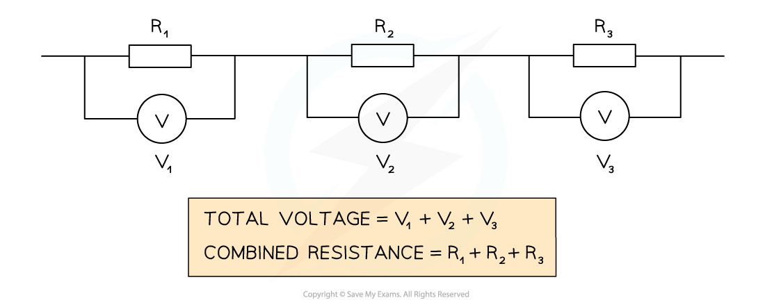
Voltage in series
The total potential difference of the power supply is shared between the components
Voltage is shared

Resistance in series
When two or more resistors are connected in series, the total resistance is equal to the sum of their individual resistances
For two resistors of resistance R1 and R2, the total resistance can be calculated using the equation:
![]()
Where:
R is the total resistance, in ohms (Ω)
Increasing the number of resistors increases the overall resistance
The charge now has more resistors to pass through
Resistance is increased
Worked Example
The combined resistance R in the following series circuit is 60 Ω.
What is the resistance value of R2?

A. 100 Ω B. 30 Ω C. 20 Ω D. 40 Ω
Answer: C
Step 1: Write down the equation for the combined resistance in series
R = R1 + R2 + R3
Step 2: Substitute the values for total resistance R and the other resistors
60 Ω = 30 Ω + R2 + 10 Ω
Step 3: Rearrange for R2
R2 = 60 Ω – 30 Ω – 10 Ω = 20 Ω
Worked Example
A student sets up a series circuit as shown below.

The cell supplies a current of 2 A to the circuit, and the fixed resistor has a resistance of 4 Ω.
(a) How much current flows through the fixed resistor?
(b) What is the reading on the voltmeter?
Answer:
Part (a)
Step 1: Recall that current is conserved in a series circuit
Since the current is conserved in a series circuit, it is the same size if measured anywhere in the series loop
This means that since the cell supplies 2 A to the circuit, the current is 2 A everywhere
Therefore, 2 A flows through the fixed resistor
Part (b)
Step 1: List the known quantities
Current I = 2 A
Resistance R = 4 Ω
Step 2: State the equation linking potential difference, resistance and current
The equation linking potential difference, resistance and current is:
V = IR
Step 3: Substitute the known values into the equation and calculate the potential difference
V = 2 × 4 = 8 V
Therefore, the voltmeter reads 8 V across the fixed resistor

You've read 0 of your 0 free revision notes
Get unlimited access
to absolutely everything:
- Downloadable PDFs
- Unlimited Revision Notes
- Topic Questions
- Past Papers
- Model Answers
- Videos (Maths and Science)
Did this page help you?