
Specified Practical: Investigating I-V Characteristics
Aim of the Experiment
- The aim of the experiment is to construct appropriate circuits to investigate the I–V characteristics of a variety of circuit components
- These include a fixed resistor at a constant temperature, a lamp and diode
Variables:
- Independent variable = Voltage, V
- Dependent variable = Current, I
- Control variables:
- Voltage of the power supply
- Use of the same equipment eg. wires, diodes
Equipment List
List of Equipment Used to Investigate the I-V Characteristics of a Range of Circuit Components
| Equipment | Purpose |
| Ammeter | To measure the current |
| Voltmeter | To measure the voltage |
| Variable resistor | To change the amount of current in the circuit |
| Fixed resistor (between 100 Ω and 500 Ω) | To determine the resistance of |
|
Diode |
To determine the resistance of |
|
Filament lamp |
To determine the resistance of |
| Voltage supply | To drive the current around the circuit |
| Wires | To complete a closed circuit |
Method
Circuit Diagram of Set-up to Investigate I-V Characteristics of Components

Circuit diagram of the apparatus set up. The fixed resistor will be replaced by a filament lamp and diode
- Set up the circuit as shown with the fixed resistor
- Vary the current across the component by changing the resistance of the variable resistor, this will change the voltage across the component
- For each voltage, record the value of the current from the ammeter 3 times and calculate the average current
- Repeat steps 2 and 3 for 8-10 different voltage values increasing by around 0.5 V each time
- Make sure to switch off the circuit in between readings to prevent heating of the component and wires
- Reverse the terminals of the power supply and take readings for the negative voltage (and therefore negative current)
- Replace the fixed resistor with the filament lamp, then the diode, repeating the experiment for each
Example Results Table

A good results table includes space for all measurements and associated calculations (like averages) presented in a clear and logical way
Analysis of Results
- Plot a graph of average current against voltage (an I–V graph) for each component
- If the I–V graph is a straight line, it is a linear conductor. This is expected from the fixed resistor
- If the I–V graph is a curve, it is a non-linear conductor. This is expected from the filament lamp and diode
- Compare the results from the graphs obtained to the known I–V graphs for the resistor, filament lamp and diode. These should look like:
I-V Graph Shapes for a Resistor, Diode & Filament Lamp

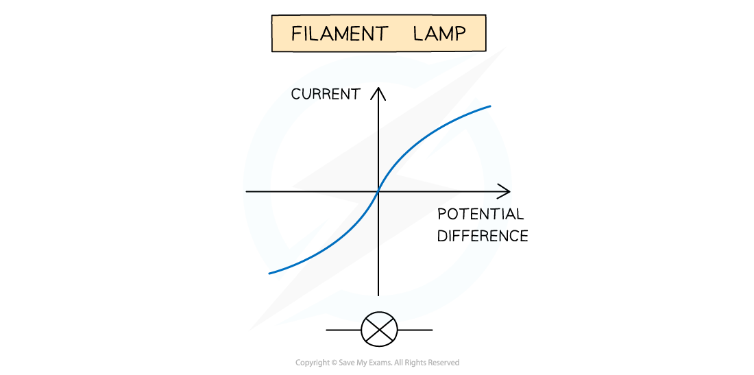
The expected I-V graphs for the resistor, diode and filament lamp
Evaluating the Experiment
Systematic Errors:
- The voltmeter and ammeters should start from zero, to avoid zero error in the readings
Random Errors:
- In practice, the voltmeter and ammeter will still have some resistance, therefore the voltages and currents displayed may be slightly inaccurate
- The temperature of the equipment could affect its resistance. This must be controlled carefully
- Taking multiple readings of the current for each component will provide a more accurate result and reduce uncertainties
Safety Considerations
- When there is a high current and a thin wire, the wire will become very hot
- Make sure you never touch the wire directly when the circuit is switched on
- Switch off the power supply right away if burning is smelled
- Make sure there are no liquids close to the experiment, as this could damage the electrical equipment
- Electrical components will get hot, especially at higher voltages
- Be careful when handling them - especially the filament lamp
- Disconnect the power supply in between readings to avoid the components heating up too much
Worked example
A student is given an unknown circuit component in a sealed box, and asked to identify it using its I-V characteristics.
(a)
Complete the labels on the circuit diagram.

(b)
The student's data is shown in the table below. Suggest the identity of the circuit component and explain your answer.
| Voltage (V) | −0.4 | −0.2 | 0.0 | 0.2 | 0.4 | 0.6 | 0.8 | 1.0 |
| Current (mA) | 0 | 0 | 0 | 0 | 0 | 4 | 16 | 40 |
Answer:
Part (a)
(i)
Fuse
(ii)
Cell
(iii)
Variable resistor
(iv)
Voltmeter
(v)
Ammeter
Part (b)
Step 1: Suggest the identify of the circuit component
- Diode / LED
Step 2: Explain your answer
- The data shows zero current for negative voltages which shows that the current only flows in one direction
- The data shows an exponential increase in current for positive voltages
- Both of these are features of the I-V characteristics of a diode
