Program Development Life Cycle - Design (CIE IGCSE Computer Science)

Revision Note

Test Yourself
Dan Turnes

Expertise

Computer Science

Decomposition

  • This is the act of breaking down a large problem into smaller, clear, manageable and understandable sub-parts. Sub-parts can be divided until they are easily solvable and cannot be broken down any further. An example of decomposition could be getting ready in the morning to go to school
    • Step 1: Wake up
    • Step 2: Get breakfast
    • Step 3: Brush teeth
    • Step 4: Put clothes on
    • Step 5: Make sure the bag and school supplies are ready
    • Step 6: Find transport to school e.g. walk, bus, car, bike, etc

  • These steps could be further subdivided, for example, “Step 2: Get breakfast” would entail:
    • Step 2.1 Get a bowl
    • Step 2.2 Get cereal
    • Step 2.3 Get milk
    • Step 2.4 Get a spoon
    • Step 2.5 Put cereal in a bowl
    • And so on…

  • Once the requirements document has been created, developers need to design the structure and algorithms to solve the problem:
    • Structure charts are created to show the breakdown of tasks in a hierarchy
    • Flowcharts may be created to visually show how tasks should be carried out
    • Pseudocode is created, sometimes from flowcharts, to allow programmers to easily translate task instructions into programming code

  • The design of a solution identifies what tasks need completing, how to complete the tasks and how each task works together with other tasks

  • A computer system includes several components that work together: software, hardware, data, networking and people 
  • Systems can be broken down into sub-systems that can be further broken down into more sub-systems, until each sub-system has a single purpose. This decomposition is known as top-down design

Decomposing a system

  • To create an overall system and solve a problem, it must first be broken down into subsystems that are easier to solve and create. The act of breaking down the problem is known as stepwise refinement
  • Decomposing the problem this way creates smaller, more manageable and more easily understandable sub-parts
  • Each sub-system can be assigned to a developer or group of developers who create subroutines from these sub-systems. Each sub-system can then be created at the same time, reducing development and testing time, especially on large projects
  • Decomposing the system using stepwise refinement requires developers to think about four key areas:
    • Inputs: data entered into the system
    • Processes: subroutines and algorithms that turn inputs and stored data into outputs
    • Outputs: data that is produced by the system, such as information on a screen or printed information
    • Storage: data that is stored on a physical device, such as on a hard drive
  • To solve a problem all aspects must be thoroughly understood by the developers
  • There are many methods used to design and construct solutions. Three such methods are illustrated below:

Structure Diagrams

  • Structure diagrams show hierarchical top-down design in a visual form. Each problem is divided into sub-problems and each sub-problem divided into further sub-problems. At each level the problem is broken down into more detailed tasks that can be implemented using a single subroutine

unnamed-3

Figure 1: A structure diagram

unnamed-4

Figure 2: A structure diagram for a mobile application

Worked example

A satellite navigation system is an example of a computer system that is made up of subsystems. Part of a satellite navigation system: allows the user to enter details for a new destination or select a previously saved destination and displays directions in the form of a visual map or as a list. Draw a structure diagram for this part of the satellite navigation system. 

[4]

  • [1] for a hierarchical structure
  • [1]  for suitable names for the sub-systems
  • [1]  for identifiable inputs
  • [1]  for identifiable outputs

unnamed-7


Flowcharts

  • Flowcharts show how algorithms can be represented visually in a diagrammatic format
  • Each flowchart has a start and an end with arrows showing the order each task or instruction needs to be carried out in
  • Flowcharts are made of several symbols:
    • Terminator symbols: Also known as Begin/End symbols. These indicate where a flowchart starts and stops
    • Process symbols: These show simple actions being performed such as assigning values or performing arithmetic operations on values
      • Processes can also represent other flowcharts or summarised actions. For example, searching or sorting a list is a complex process which would require its own flowchart. A process symbol could be used to represent sorting or searching in a separate flowchart. This is represented by a process with an additional bar on either side of the symbol
    • Input/Output symbols: These show the input of data and output of data
    • Decision symbols: These symbols are used to decide whether to take one of two routes by answering a true/false or yes/no question. They can be used for selection and iteration
    • Flow lines: Flow lines use arrows to show the direction of flow and what task to perform next. Usually these are top to bottom and left to right

unnamed-5

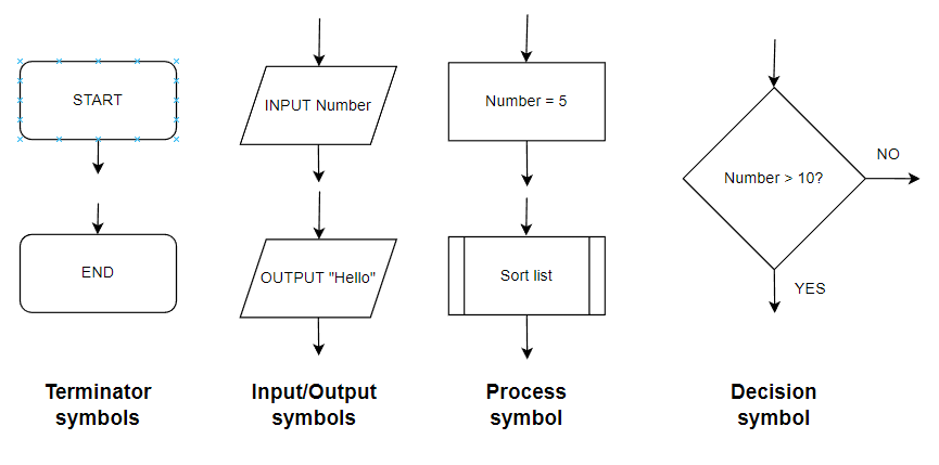
Figure 3: Flowchart symbols: terminator, input/output, process, decision (left to right)

unnamed-6

Figure 4: Flowchart for finding the largest of ten numbers

Pseudocode

  • Pseudocode is a programming-like language that does not have syntax. It can be considered “fake” code.
  • It uses english words and phrases to represent instructions and is very similar to programming code but does not and cannot run on any computer
  • The purpose of pseudocode is to allow developers to understand how to create a program regardless of the programming language used to implement the solution
  • While pseudocode has no specific syntax, it is important to stick to a consistent style. This will make it easier and quicker for programmers to read and create programs from the pseudocode
    • Examples of a consistent style can include:
      • Keywords are written in capital letters e.g. INPUT, OUTPUT, IF, THEN, ELSE
      • Variable and subroutine names start with capital letters e.g. Age, Name, Date, CalculateArea, Sortlist
      • Indentation can be used for iteration and selection

You've read 0 of your 0 free revision notes

Get unlimited access

to absolutely everything:

  • Downloadable PDFs
  • Unlimited Revision Notes
  • Topic Questions
  • Past Papers
  • Model Answers
  • Videos (Maths and Science)

Join the 100,000+ Students that ❤️ Save My Exams

the (exam) results speak for themselves:

Did this page help you?

Dan Turnes

Author: Dan Turnes

Dan graduated from the University of York with a BEng in Computer Science and has been a teacher and tutor of GCSE and A-Level Computer Science in the Yorkshire area for over six years. His goals are to engage students in the science of learning and to enable them to enjoy the experience. Dan's continued practice has brought him to SME to create high quality resources and support students to achieve their potential in Computer Science.