
Core Practical 4: Investigating & Testing Circuits
Equipment List

- Resolution of measuring equipment:
- Variable resistor = 0.005 Ω
- Voltmeter = 0.1 V
- Ammeter = 0.01 A
Experiment 1: Investigating Potential Difference, Current & Resistance
Aim of the Experiment
- The aim of the experiment is to investigate the relationship between potential difference, current and resistance for a resistor and a filament lamp
Variables:
- Independent variable = Potential difference, V
- Dependent variable = Current, I
- Control variables:
- Potential difference of the power supply
- Use of the same equipment e.g. wires
Method

Circuit diagram of the apparatus set up. The fixed resistor will be replaced by a filament lamp
- Set up the circuit as shown with the fixed resistor
- Vary the voltage across the component by changing the resistance of the variable resistor, using a wide range of voltages (between 8-10 readings). Check the appropriate voltage reading on the voltmeter
- For each voltage, record the value of the current from the ammeter 3 times and calculate the average current
- Increase the voltage further in steps of 0.5 V and repeat steps 2 and 3
- Make sure to switch off the circuit in between readings to prevent heating of the component and wires
- Reverse the terminals of the power supply and take readings for the negative voltage (and therefore negative current)
- Replace the fixed resistor with the filament lamp and repeat the experiment from step 1
- An example of a suitable table might look like this:

Analysis of Results
- Plot a graph of average current against voltage (an I–V graph) for each component
- If the I–V graph is a straight line through the origin, current is directly proportional to voltage. This is expected from the fixed resistor:
- The equation that relates the voltage to the current is given by:
V = IR
- This equation shows that V is proportional to I (i.e. if voltage increases, current increases at the same rate) if R is constant, which is true for a fixed resistor
- If the I-V graph is curved, then current is not directly proportional to voltage
- This is expected from the filament lamp
- As the current increases through a filament lamp, its temperature increases
- This increases the resistance of the filament, so it does not remain constant
- Compare the results from the graphs obtained to the known I–V graphs for the resistor, filament lamp and diode. These should look like:

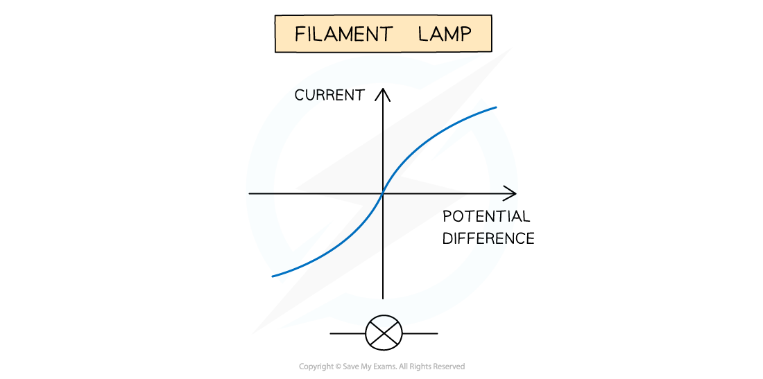
The expected I-V graphs for the resistor, diode and filament lamp
Experiment 2: Testing Series & Parallel Circuits
Aim of the Experiment
- The aim of the experiment is to test series and parallel circuits using resistors and filament lamps. There are a variety of methods to test series and parallel circuits but this starts with a single resistor / filament lamp in series with a cell, and builds on this circuit with an additional resistor in series or in parallel.
Variables:
- Independent variable = Potential difference, V
- Dependent variable = Current, I
- Control variables:
- Potential difference of the power supply
- Use of the same equipment e.g. wires
Method

Circuit diagram of the apparatus set up. The fixed resistors will be replaced by a filament lamps
- Set up the circuit as shown with the single fixed resistor
- Record the voltage using the voltmeter and the current using the ammeter
- For each pair of voltage and current, calculate the resistance and record this
- Change the resistor and repeat step 2 and 3
- Arrange the two resistors in series as shown in the image, then repeat step 2
- Arrange the two resistors in parallel as shown in the image, then repeat step 2
- Replace the fixed resistor with a filament lamp and repeat the experiment from step 1
- An example of a suitable table might look like this:

Analysis of Results
- The value of the resistance for each voltage and current reading is calculated using the equation:

- In series, the total resistance of the two resistors is equal to the sum of the two individual resistances
- In parallel, the total resistance of the two resistors is less than either of the two individual resistances
Evaluating the Experiment
Systematic Errors:
- The voltmeter and ammeters should start from zero, to avoid zero error in the readings
Random Errors:
- In practice, the voltmeter and ammeter will still have some resistance, therefore the voltages and currents displayed may be slightly inaccurate
- The temperature of the equipment could affect its resistance. This must be controlled carefully
- Taking multiple readings of the current for each component will provide a more accurate result and reduce uncertainties
Safety Considerations
- When there is a high current and a thin wire, the wire will become very hot
- Make sure never to touch the wire directly when the circuit is switched on
- Switch off the power supply right away if burning is smelled
- Make sure there are no liquids close to the equipment, as this could damage the electrical equipment
- The components will get hot especially at higher voltages
- Be careful when handling them - especially the filament lamp
- Disconnect the power supply in between readings to avoid the components heating up too much
