IV Graphs (Edexcel IGCSE Physics: Double Science)
Revision Note

Author
AshikaExpertise
Physics Project Lead
IV Graphs
- As the potential difference across a component is increased, the current also increases
- This is because potential difference and current are proportional
- The precise relationship between voltage and current is different for different components and can be shown on an IV graph, including in:
- Fixed resistors & wires
- Filament lamps
- Diodes
Fixed Resistors & Wires
- The current through a fixed resistor or a wire increases as the potential difference (or voltage) across it increases
- In other words, current is directly proportional to the potential difference for a fixed resistor (or a wire)
- This relationship is true because the resistance of the fixed resistor (or wire) stays constant
- An IV graph shows that the line is straight and goes through the origin, as shown in the image below:

IV graph for a fixed resistor. The current is directly proportional to the potential difference (voltage) as the graph is a straight line through the origin
Filament Lamps
- For a filament lamp, current and voltage are not directly proportional
- This is because the resistance of the filament lamp increases as the temperature of the filament increases
- The IV graph for a filament lamp shows the current increasing at a proportionally slower rate than the potential difference
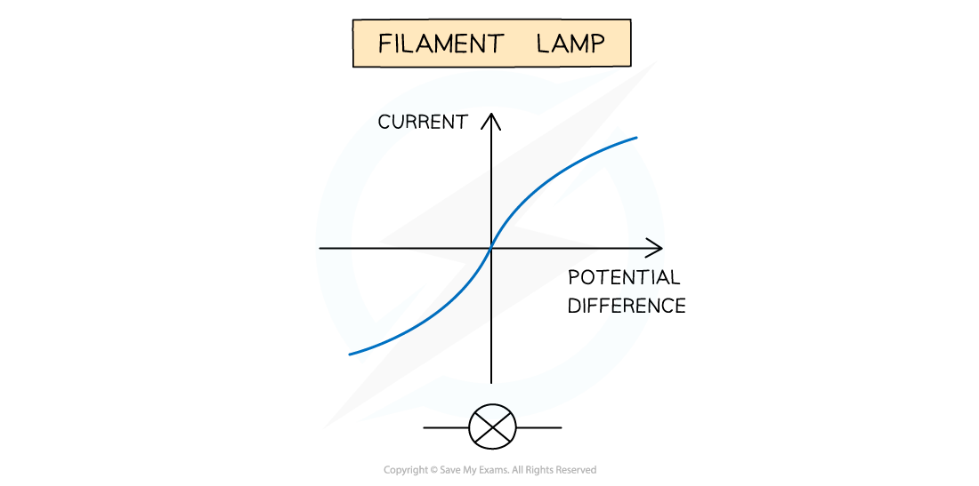
IV graph for a filament lamp
- This is because:
- As the current increases, the temperature of the filament in the lamp increases
- The higher temperature causes the atoms in the metal lattice of the filament to vibrate more
- This causes an increase in resistance as it becomes more difficult for free electrons (the current) to pass through
- Resistance opposes the current, causing the current to increase at a slower rate
- Where the graph is a straight line, the resistance is constant
- The resistance increases as the graph curves
- Reversing the potential difference reverses the current and makes no difference to the shape of the curve
Diodes
- A diode allows current to flow in one direction only
- This is called forward bias
- In the reverse direction, the diode has very high resistance, and therefore no current flows
- This is called reverse bias
- The IV graph for a diode is slightly different:
- When the current is in the direction of the arrowhead symbol, this is forward bias
- This is shown by the sharp increase in potential difference and current on the right side of the graph
- When the diode is switched around, this is reverse bias
- This is shown by a zero reading of current or potential difference on the left side of the graph
- When the current is in the direction of the arrowhead symbol, this is forward bias

IV graph for a semiconductor diode
Investigating IV Graphs Experimentally
- In order to investigate the relationship between current and voltage different components, the following equipment is required:
- An ammeter - to measure the current through the component
- A voltmeter - to measure the voltage across the component
- A variable resistor - to vary the current through the circuit
- Power source - to provide a source of potential difference (voltage)
- Wires - to connect the components together in a circuit
- The image below shows the circuits set up to obtain IV graphs for a filament lamp and a diode

These circuits enable the investigation of current and voltage for a filament lamp or diode to be investigated
- The current is the independent variable
- The variable resistor is used to change the current flowing through the filament lamp / diode
- The voltage is the dependent variable
- The voltmeter is used to measure the voltage across the filament lamp / diode
- Recording measurements of current and voltage as the current increases enables an IV graph to be plotted for each component
Resistance
- Resistance is the opposition to the flow of current
- The higher the resistance of a circuit the lower the current
- Resistors come in two types:
- Fixed resistors
- Variable resistors
- Fixed resistors have a resistance that remains constant
- Variable resistors can change the resistance by changing the length of wire that makes up the circuit
- A longer length of wire has more resistance than a shorter length of wire

Fixed and variable resistor circuit symbols

You've read 0 of your 0 free revision notes
Get unlimited access
to absolutely everything:
- Downloadable PDFs
- Unlimited Revision Notes
- Topic Questions
- Past Papers
- Model Answers
- Videos (Maths and Science)
Did this page help you?