Magnetic Force on a Current-Carrying Conductor
- A current-carrying conductor produces its own magnetic field
- When interacting with an external magnetic field, it will experience a force
- A current-carrying conductor will only experience a force if the current through it is perpendicular to the direction of the magnetic field lines
- A simple situation would be a copper rod placed within a uniform magnetic field
- When current is passed through the copper rod, it experiences a force that makes it move
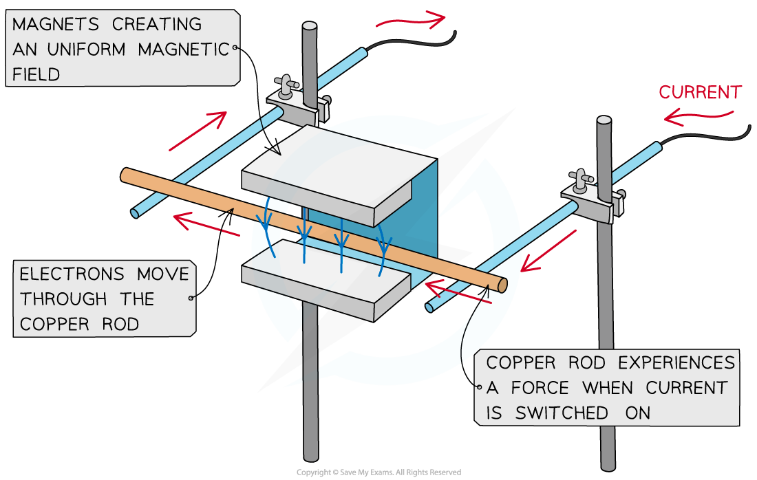
A copper rod moves within a magnetic field when current is passed through it
Calculating Magnetic Force on a Current-Carrying Conductor
- The strength of a magnetic field is known as the magnetic flux density, B
- This is also known as the magnetic field strength
- It is measured in units of Tesla (T)
- The force F on a conductor carrying current I at right angles to a magnetic field with flux density B is defined by the equation
F = BIL sinθ
- Where:
- F = force on a current carrying conductor in a magnetic field (N)
- B = magnetic flux density of external magnetic field (T)
- I = current in the conductor (A)
- L = length of the conductor (m)
- θ = angle between the conductor and external magnetic field (degrees)
- This equation shows that the greater the current or the magnetic field strength, the greater the force on the conductor
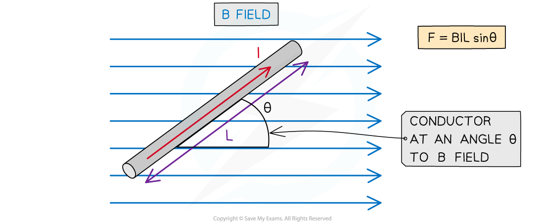
Magnitude of the force on a current carrying conductor depends on the angle of the conductor to the external B field
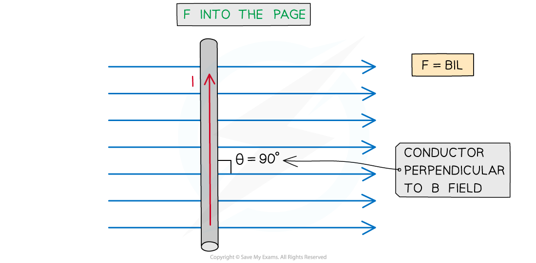
- The maximum force occurs when sin θ = 1
- This means θ = 90o and the conductor is perpendicular to the B field
- This equation for the magnetic force now becomes:
F = BIL
- The minimum force (0) is when sin θ = 0
- This means θ = 0o and the conductor is parallel to the B field
- It is important to note that a current-carrying conductor will experience no force if the current in the conductor is parallel to the field
Worked example
A current of 0.87 A flows in a wire of length 1.4 m placed at 30o to a magnetic field of flux density 80 mT.Calculate the force on the wire.
Step 1: Write down the known quantities
Magnetic flux density, B = 80 mT = 80 × 10-3 T
Current, I = 0.87 A
Length of wire, L = 1.4 m
Angle between the wire and the magnetic field, θ = 30o
Step 2: Write down the equation for force on a current-carrying conductor
F = BIL sinθ
Step 3: Substitute in values and calculate
F = (80 × 10-3) × (0.87) × (1.4) × sin(30) = 0.04872 = 0.049 N (2 s.f)
Origin of the Forces Between Current-Carrying Conductors
- A current carrying conductor, such as a wire, produces a magnetic field around it
- The direction of the field depends on the direction of the current through the wire
- This is determined by the right hand thumb rule
- Parallel current-carrying conductors will therefore either attract or repel each other
- If the currents are in the same direction in both conductors, the magnetic field lines between the conductors cancel out – the conductors will attract each other
- If the currents are in the opposite direction in both conductors, the magnetic field lines between the conductors push each other apart – the conductors will repel each other

Both wires will attract if their currents are in the same direction and repel if in opposite directions
- When the conductors attract, the direction of the magnetic forces will be towards each other
- When the conductors repel, the direction of the magnetic forces will be away from each other
- The magnitude of each force depend on the amount of current and length of the wire
Worked example
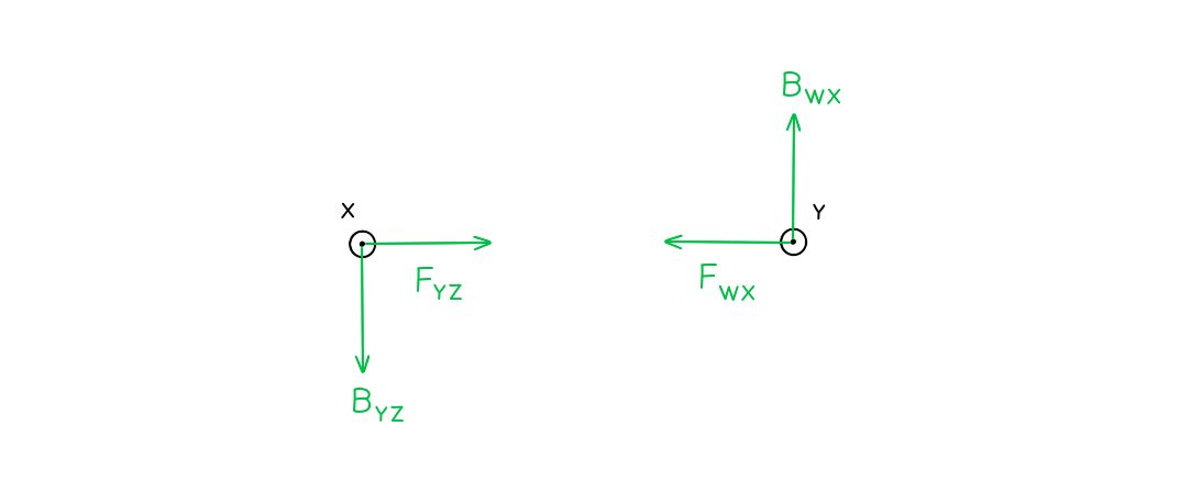
Two long, straight, current-carrying conductors, WX and YZ, are held at a close distance, as shown in diagram 1. The conductors each carry the same magnitude current in the same direction. A plan view from above the conductors is shown in diagram 2.
 On diagram 2, draw arrows, one in each case, to show the direction of:
- The magnetic field at X due to the current in wire YZ (label this arrow BYZ)
- The force at X as a result of the magnetic field due to the current in the wire YZ (label this arrow FYZ)
- The magnetic field at Y due to the current in wire WX (label this arrow BWX)
- The force at Y as a result of the magnetic field due to the current in the wire WX (label this arrow FWX)
- Newton’s Third Law states:
- When two bodies interact, the force on one body is equal but opposite in direction to the force on the other body
- Therefore, the forces on the wires act in equal but opposite directions
Exam Tip
Remember that the direction of current flow is the flow of positive charge (positive to negative), and this is in the opposite direction to the flow of electrons

