Potential Divider Circuits
- When two resistors are connected in series, through Kirchhoff’s Second Law, the potential difference across the power source is divided between them
- Potential dividers are circuits that can produce an output voltage as a fraction of its input voltage
- The main purposes of a potential divider are:
- To provide a variable potential difference
- To enable a specific potential difference to be chosen
- To split the potential difference of a power source between two or more components
- Potential dividers have a wide range of applications in devices requiring features such as volume control and sensory circuits
- This can be achieved using components such as LDRs and thermistors
- Potential divider circuits are based on the ratio of voltage between components
- This is equal to the ratio of the resistances of the resistors in the diagram below, giving the following equation:
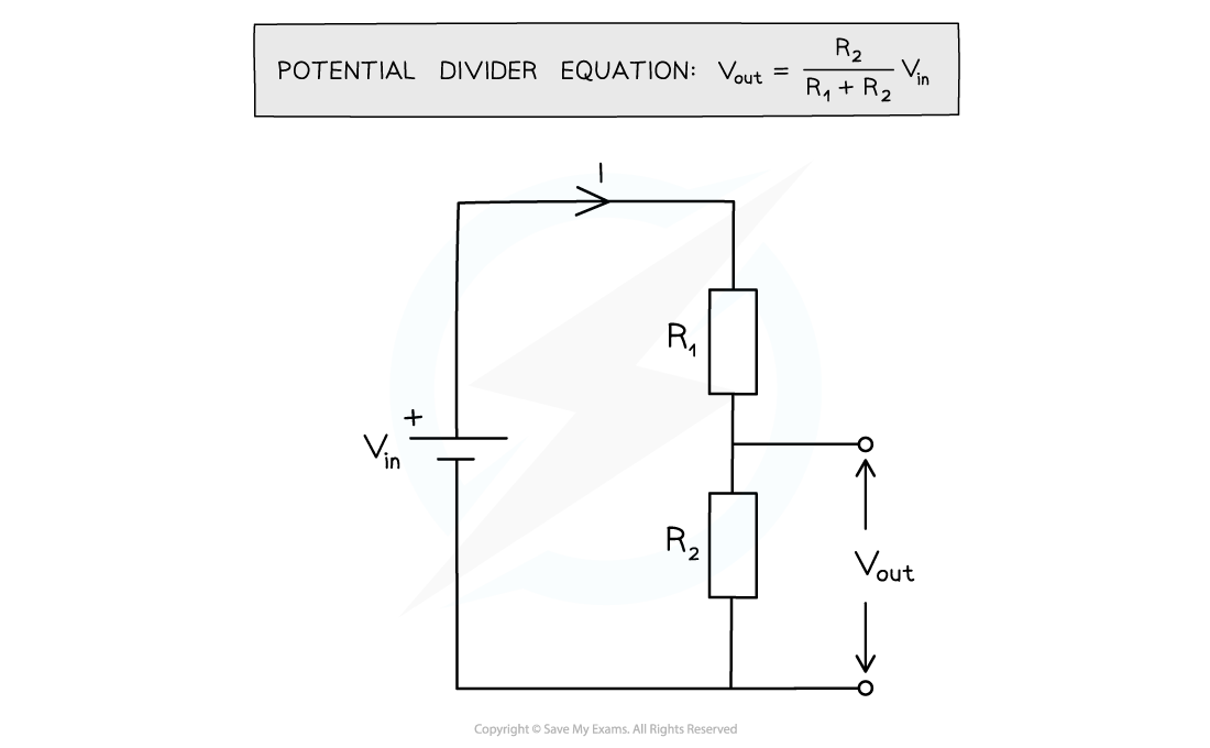
Potential divider diagram and equation
- The input voltage Vin is applied to the top and bottom of the series resistors
- The output voltage Vout is measured from the centre to the bottom of resistor R2
- The potential difference V across each resistor depends upon its resistance R:
- The resistor with the largest resistance will have a greater potential difference than the other one from V = IR
- If the resistance of one of the resistors is increased, it will get a greater share of the potential difference, whilst the other resistor will get a smaller share
- In potential divider circuits, the p.d across a component is proportional to its resistance from V = IR
Worked example
The circuit is designed to light up a lamp when the input voltage exceed a preset value.
It does this by comparing Vout with a fixed reference voltage of 5.3 V.

Vout is equal to 5.3
Calculate the input voltage Vin.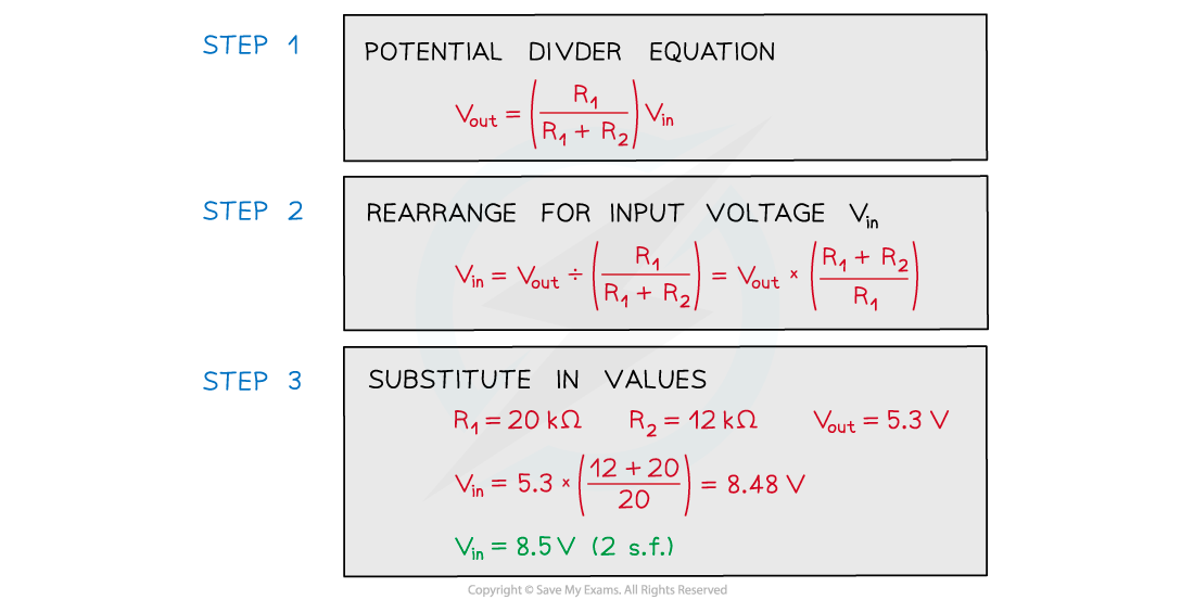
Exam Tip
Always make sure the correct resistance is in the numerator of the potential divider equation. This will be the resistance of the component you want to find the output voltage of.

