CIE AS Physics

Revision Notes

Syllabus Edition

First teaching 2020

Last exams 2024

|

10.2.2 Potential Divider Components

Test Yourself

The Potentiometer

  • A potentiometer is similar to a variable resistor connected as a potential divider to give a continuously variable output voltage
  • It can be used as a means of comparing potential differences in different parts of the circuit
  • The circuit symbol is recognised by an arrow next to the resistor

Potentiometer symbol, downloadable AS & A Level Physics revision notes

Potentiometer circuit diagram

  • A potentiometer is a single component that (in its simplest form) consists of a coil of wire with a sliding contact, midway along it

Potentiometer diagram, downloadable AS & A Level Physics revision notes

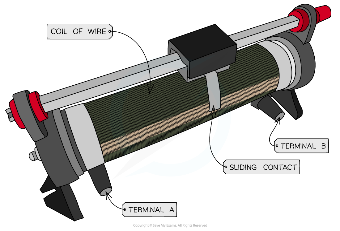
A potentiometer is a type of variable resistor

  • It is recognised on a circuit diagram with a resistor fitted with a sliding contact
  • The sliding contact has the effect of separating the potentiometer into two parts (an upper part and a lower part), both of which have different resistances

Potentiometer circuit diagram, downloadable AS & A Level Physics revision notes

Moving the slider (the arrow in the diagram) changes the resistance (and hence potential difference) of the upper and lower parts of the potentiometer


  • If the slider in the above diagram is moved upwards, the resistance of the lower part will increase and so the potential difference across it will also increase
  • Therefore, the variable resistor obtains a maximum or minimum value for the output voltage
  • If the resistance is 3 Ω:
    • Maximum voltage is when the resistance is 3 Ω
    • Minimum voltage is when the resistance is 0 Ω

Worked example

A potential divider circuit consists of fixed resistors of resistance 5.0 Ω and 7.0 Ω connected in series with a 6.0 Ω resistor fitted with a sliding contact. These are connected across a battery of e.m.f 12 V and zero internal resistance, as shown.What are the maximum and minimum output voltages of this potential divider circuit?

ANSWER:   A

Worked example - potentiometer (2), downloadable AS & A Level Physics revision notes

The Galvanometer

  • A galvanometer is a type of sensitive ammeter used to detect electric current
  • It is used in a potentiometer to measure e.m.f between two points in a circuit
  • The circuit symbol is recognised by an arrow in a circle:


Galvanometer circuit symbol, downloadable AS & A Level Physics revision notes

Galvanometer circuit symbol

  • A galvanometer is made from a coil of wire wrapped around an iron core that rotates inside a magnetic field:


Galvanometer, downloadable AS & A Level Physics revision notes

The galvanometer

  • The arrow represents a needle which deflects depending on the amount of current passing through
    • When the arrow is facing directly upwards, there is no current
    • This is called null deflection

  • Ohm’s law tells us that the current through a conductor (wire) is directly proportional to the potential difference through it i.e. no p.d means no current flows through the galvanometer
  • A galvanometer has p.d of zero when the potential on one side equals the potential on the other side
  • This is at the position at which it is connected on the wire (which varies with the sliding contact) gives a p.d equal to the EMF of the cell connected to the galvanometer
  • The cell should be connected such that its potential opposes the potential on the wire i.e. the positive terminal of the power supply faces the positive terminal of the cell:

Galvanometer circuit diagram, downloadable AS & A Level Physics revision notes 

  • When the sliding contact moves along the potentiometer wire, you add or remove resistance from/to the external circuit. This changes the potential drop across X and Y
  • Location of the sliding point is adjusted until the galvanometer reads zero. This is until the potential difference equals E2
  • The direction of the two e.m.fs oppose each other and there is no current

Worked example

A power supply and a cell are compared using the potentiometer circuit shown.The e.m.f produced by the cell is measured on the potentiometer. The potentiometer wire AB is 150.0 cm long and has a resistance of 2.4 Ω. The power supply has an e.m.f of 5.000 V and the solar cell has an e.m.f of 6.25 mV.Which resistance R must be used so that the galvanometer reads zero when AS = 32.0 cm?A. 735 Ω               B. 451 Ω               C. 207 Ω               D. 401 Ω

ANSWER:   D

Worked example - Galvanometer (2), downloadable AS & A Level Physics revision notes

Exam Tip

If you’re unsure as to whether the p.d will increase as the contact slider is moved along the wire, remember p.d is proportional to the length of the wire (from Ohm’s law and the resistivity equation). The longer the length of a wire, the higher the p.d

You've read 0 of your 0 free revision notes

Get unlimited access

to absolutely everything:

  • Downloadable PDFs
  • Unlimited Revision Notes
  • Topic Questions
  • Past Papers
  • Model Answers
  • Videos (Maths and Science)

Join the 100,000+ Students that ❤️ Save My Exams

the (exam) results speak for themselves:

Did this page help you?

Katie M

Author: Katie M

Katie has always been passionate about the sciences, and completed a degree in Astrophysics at Sheffield University. She decided that she wanted to inspire other young people, so moved to Bristol to complete a PGCE in Secondary Science. She particularly loves creating fun and absorbing materials to help students achieve their exam potential.