Principles of Electromagnetic Induction
- Electromagnetic induction is a phenomenon which occurs when an e.m.f is induced when a conductor moves through a magnetic field
- When the conductor cuts through the magnetic field lines:
- This causes a change in magnetic flux
- Which causes work to be done
- This work is then transformed into electrical energy
- Therefore, if attached to a complete circuit, a current will be induced
- This is known as electromagnetic induction and is defined as:
The process in which an e.m.f is induced in a closed circuit due to changes in magnetic flux
- This can occur either when:
- A conductor cuts through a magnetic field
- The direction of a magnetic field through a coil changes
- Electromagnetic induction is used in:
- Electrical generators which convert mechanical energy to electrical energy
- Transformers which are used in electrical power transmission
- This phenomenon can easily be demonstrated with a magnet and a coil, or a wire and two magnets
Experiment 1: Moving a magnet through a coil
- When a coil is connected to a sensitive voltmeter, a bar magnet can be moved in and out of the coil to induce an e.m.f
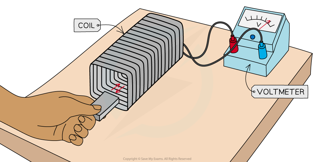
A bar magnet is moved through a coil connected to a voltmeter to induce an e.m.f
The expected results are:
- When the bar magnet is not moving, the voltmeter shows a zero reading
- When the bar magnet is held still inside, or outside, the coil, the rate of change of flux is zero, so, there is no e.m.f induced
- When the bar magnet begins to move inside the coil, there is a reading on the voltmeter
- As the bar magnet moves, its magnetic field lines ‘cut through’ the coil, generating a change in magnetic flux
- This induces an e.m.f within the coil, shown momentarily by the reading on the voltmeter
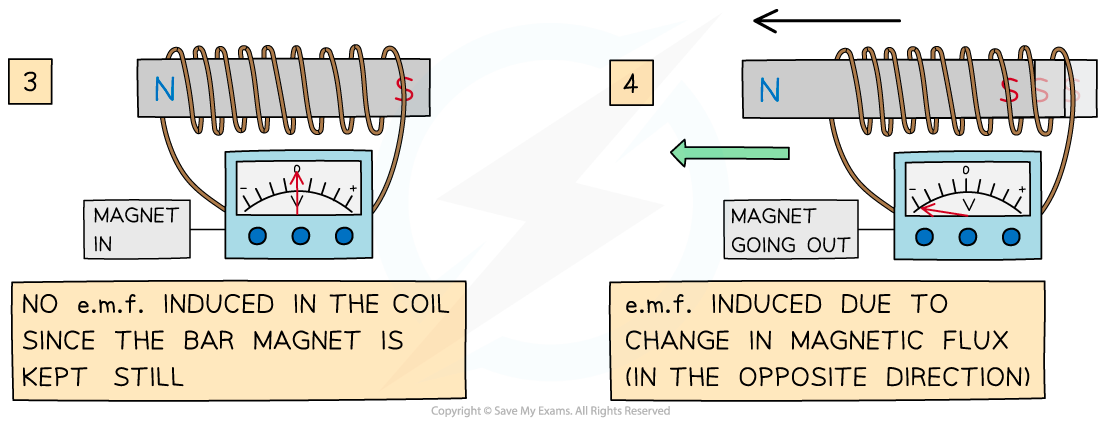
- When the bar magnet is taken back out of the coil, an e.m.f is induced in the opposite direction
- As the magnet changes direction, the direction of the current changes
- The voltmeter will momentarily show a reading with the opposite sign
- Increasing the speed of the magnet induces an e.m.f with a higher magnitude
- As the speed of the magnet increases, the rate of change of flux increases
- The direction of the electric current, and e.m.f, induced in the conductor is such that it opposes the change that produces it
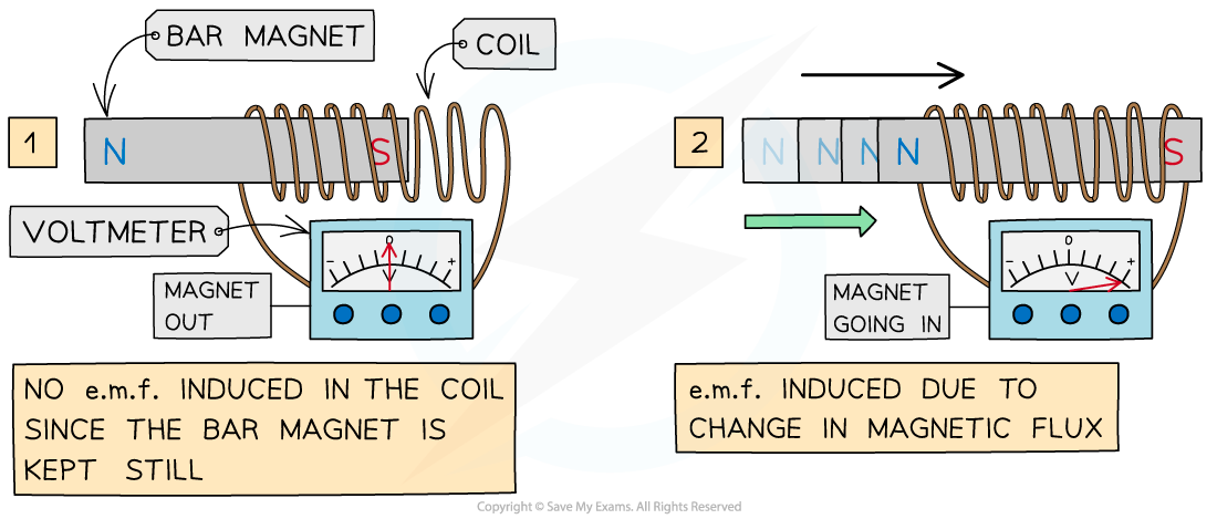
An e.m.f is induced only when the bar magnet is moving through the coil
- Factors that will increase the induced e.m.f are:
- Moving the magnet faster through the coil
- Adding more turns to the coil
- Increasing the strength of the bar magnet
Experiment 2: Moving a wire through a magnetic field
- When a long wire is connected to a voltmeter and moved between two magnets, an e.m.f is induced
- Note: there is no current flowing through the wire to start with

A wire is moved between two magnets connected to a voltmeter to induce an e.m.f
The expected results are:
- When the wire is not moving, the voltmeter shows a zero reading
- When the wire is held still inside, or outside, the magnets, the rate of change of flux is zero, so, there is no e.m.f induced
- As the wire is moved through between the magnets, an e.m.f is induced within the wire, shown momentarily by the reading on the voltmeter
- As the wire moves, it ‘cuts through’ the magnetic field lines of the magnet, generating a change in magnetic flux
- When the wire is taken back out of the magnet, an e.m.f is induced in the opposite direction
- As the wire changes direction, the direction of the current changes
- The voltmeter will momentarily show a reading with the opposite sign
- As before, the direction of the electric current, and e.m.f, induced in the conductor is such that it opposes the change that produces it
- Factors that will increase the induced e.m.f are:
- Increasing the length of the wire
- Moving the wire between the magnets faster
- Increasing the strength of the magnets

