Magnetic Flux, Flux Density & Flux Linkage
Magnetic Flux Density
- The strength of a magnetic field is defined by the density of the magnetic field lines, or magnetic flux density, at that point
- Magnetic flux density is defined by the symbol B
- It is measured in Tesla (T)
- Rearranging the equation for magnetic force on a wire, the magnetic flux density is defined by the equation:

- Where:
- B = magnetic flux density (T)
- F = magnetic force on a current-carrying wire (N)
- I = current (A)
- L = length of the wire (m)
- For reference, the Earth's magnetic flux density is around 0.032 mT and an ordinary fridge magnet is around 5 mT
- The magnetic flux density is sometimes referred to as the magnetic field strength
Magnetic Flux
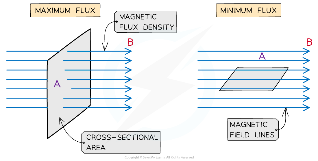
- Magnetic flux is a quantity which signifies how much of a magnetic field passes perpendicularly through some area
- For example, the amount of magnetic flux through a rotating coil will vary as the coil rotates in the magnetic field
- It is a maximum when the magnetic field lines are perpendicular to the coil area
- It is at a minimum when the magnetic field lines are parallel to the coil area
- The magnetic flux is defined as:
The product of the magnetic flux density and the cross-sectional area perpendicular to the direction of the magnetic flux density
- Magnetic flux is defined by the symbol Φ (greek letter ‘phi’)
- It is measured in units of Webers (Wb)
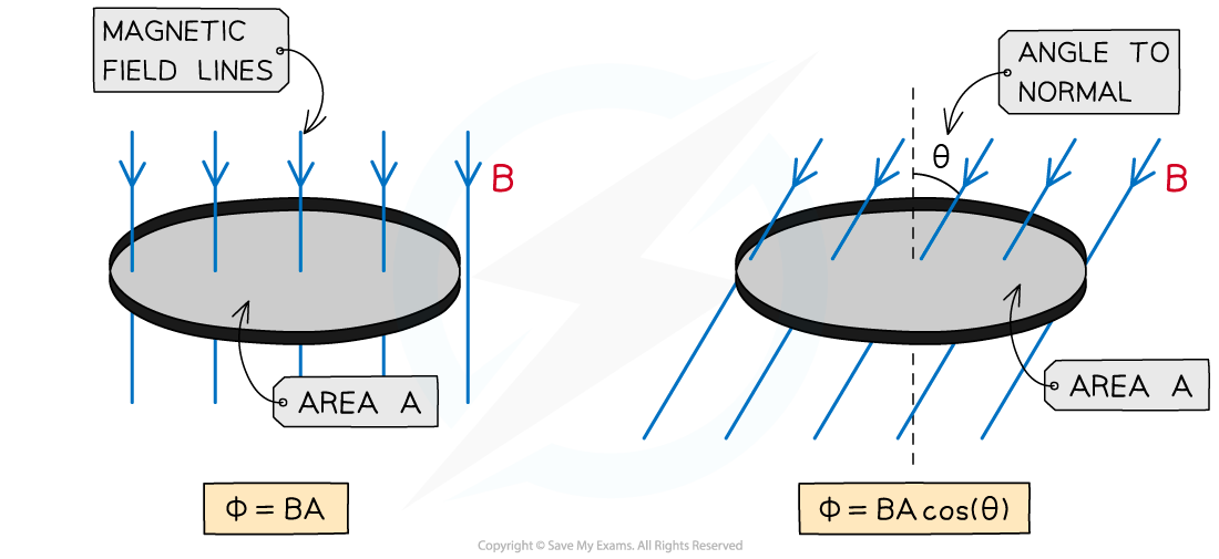
- Magnetic flux can be calculated using the equation:
Φ = BA
- Where:
- Φ = magnetic flux (Wb)
- B = magnetic flux density (T)
- A = cross-sectional area (m2)
The magnetic flux is maximised when the magnetic field lines and the area through which they are passing through are perpendicular
- When magnetic flux is not completely perpendicular to the area A, then the component of magnetic flux density B perpendicular to the area is taken
- The equation then becomes:
Φ = BA cos(θ)
- Where:
- θ = angle between magnetic field lines and the line perpendicular to the plane of the area (often called the normal line) (degrees)
The magnetic flux decreases as the angle between the field lines and perpendicular decrease
- This means the magnetic flux is:
- Maximum = BA when cos(θ) =1 therefore θ = 0o. The magnetic field lines are perpendicular to the plane of the area
- Minimum = 0 when cos(θ) = 0 therefore θ = 90o. The magnetic fields lines are parallel to the plane of the area
- An e.m.f is induced in a circuit when the magnetic flux linkage changes with respect to time
- This means an e.m.f is induced when there is:
- A changing magnetic flux density B
- A changing cross-sectional area A
- A change in angle θ
Flux Linkage
- The magnetic flux linkage is a quantity commonly used for solenoids which are made of N turns of wire
- The flux linkage is defined as:
The product of the magnetic flux and the number of turns of the coil
- It is calculated using the equation:
Flux linkage = ΦN = BAN
- Where:
- Φ = magnetic flux (Wb)
- N = number of turns of the coil
- B = magnetic flux density (T)
- A = cross-sectional area (m2)
- The flux linkage ΦN has the units of Weber turns (Wb turns)
Worked example
An aluminium window frame has a width of 40 cm and length of 73 cm as shown in the figure below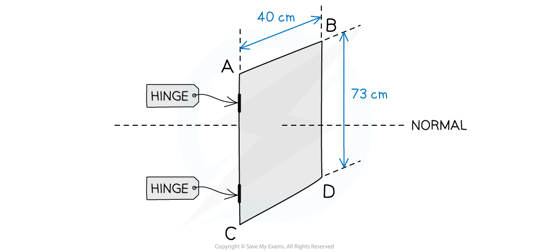 The frame is hinged along the vertical edge AC. When the window is closed, the frame is normal to the Earth’s magnetic field with magnetic flux density 1.8 × 10⁻⁵ T
a) Calculate the magnetic flux through the window when it is closed
b) Sketch the graph of the magnetic flux against angle between the field lines and the normal when the window is opened and rotated by 180°
Part (a)
Step 1: Write out the known quantities
Cross-sectional area, A = 40 cm × 73 cm = (40 × 10-2) × (73 × 10-2) = 0.292 m2
Magnetic flux density, B = 1.8 × 10⁻⁵ T
Step 2: Write down the equation for magnetic flux
Φ = BA
Step 3: Substitute in values
Φ = (1.8 × 10-5) × 0.292 = 5.256 × 10-6 = 5.3 × 10⁻⁶ Wb
Part (b)
The magnetic flux will be at a minimum when the window is opened by 90o and a maximum when fully closed or opened to 180o

Worked example
A solenoid of circular cross-sectional radius 0.40 m and 300 turns is placed perpendicular to a magnetic field with a magnetic flux density of 5.1 mT.
Determine the magnetic flux linkage for this solenoid.
Step 1: Write out the known quantities
-
- Cross-sectional area, A = πr2 = π(0.4)2 = 0.503 m2
- Magnetic flux density, B = 5.1 mT
- Number of turns of the coil, N = 300 turns
Step 2: Write down the equation for the magnetic flux linkage
ΦN = BAN
Step 3: Substitute in values and calculate
ΦN = (5.1 × 10-3) × 0.503 × 300 = 0.7691 = 0.8 Wb turns (2 s.f)
Exam Tip
Consider carefully the value of θ, it is the angle between the field lines and the line normal (perpendicular) to the plane of the area the field lines are passing through. If it helps, drawing the normal on the area provided will help visualise the correct angle.
Just like for magnetic flux, the flux linkage through a coil may not be entirely perpendicular.
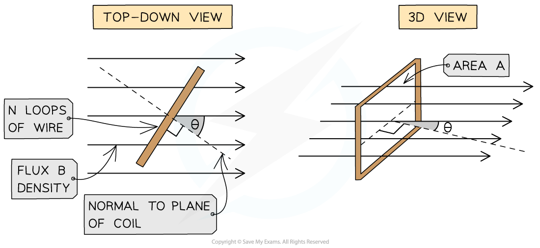
The magnetic flux linkage through a rectangular coil decreases as the angle between the field lines and a normal line to the coil plane decreases
In this case, you can just substitute the equation for B into the equation for φN, such that the flux linkage is calculated by:
format('truetype')%3Bfont-weight%3Anormal%3Bfont-style%3Anormal%3B%7D%3C%2Fstyle%3E%3C%2Fdefs%3E%3Ctext%20fill%3D%22%23FFFFFF%22%20font-family%3D%22Times%20New%20Roman%22%20font-size%3D%2218%22%20font-style%3D%22italic%22%20text-anchor%3D%22middle%22%20x%3D%226.5%22%20y%3D%2216%22%3E%26%23x3A6%3B%3C%2Ftext%3E%3Ctext%20fill%3D%22%23FFFFFF%22%20font-family%3D%22Times%20New%20Roman%22%20font-size%3D%2218%22%20font-style%3D%22italic%22%20text-anchor%3D%22middle%22%20x%3D%2219.5%22%20y%3D%2216%22%3EN%3C%2Ftext%3E%3Ctext%20fill%3D%22%23FFFFFF%22%20font-family%3D%22math17f39f8317fbdb1988ef4c628eb%22%20font-size%3D%2216%22%20text-anchor%3D%22middle%22%20x%3D%2235.5%22%20y%3D%2216%22%3E%3D%3C%2Ftext%3E%3Ctext%20fill%3D%22%23FFFFFF%22%20font-family%3D%22Times%20New%20Roman%22%20font-size%3D%2218%22%20font-style%3D%22italic%22%20text-anchor%3D%22middle%22%20x%3D%2250.5%22%20y%3D%2216%22%3EB%3C%2Ftext%3E%3Ctext%20fill%3D%22%23FFFFFF%22%20font-family%3D%22Times%20New%20Roman%22%20font-size%3D%2218%22%20font-style%3D%22italic%22%20text-anchor%3D%22middle%22%20x%3D%2262.5%22%20y%3D%2216%22%3EA%3C%2Ftext%3E%3Ctext%20fill%3D%22%23FFFFFF%22%20font-family%3D%22Times%20New%20Roman%22%20font-size%3D%2218%22%20font-style%3D%22italic%22%20text-anchor%3D%22middle%22%20x%3D%2275.5%22%20y%3D%2216%22%3EN%3C%2Ftext%3E%3Ctext%20fill%3D%22%23FFFFFF%22%20font-family%3D%22Times%20New%20Roman%22%20font-size%3D%2218%22%20text-anchor%3D%22middle%22%20x%3D%2295.5%22%20y%3D%2216%22%3Ecos%3C%2Ftext%3E%3Ctext%20fill%3D%22%23FFFFFF%22%20font-family%3D%22Times%20New%20Roman%22%20font-size%3D%2218%22%20font-style%3D%22italic%22%20text-anchor%3D%22middle%22%20x%3D%22115.5%22%20y%3D%2216%22%3E%26%23x3B8%3B%3C%2Ftext%3E%3C%2Fsvg%3E)
As before, you should remember that since cos (0°) = 1, the flux linkage is a maximum when the angle θ is zero. This means the flux and coil face are perpendicular (i.e. the normal line to the coil face and the flux lines are parallel).

