Variable Resistance Components
- Variable and sensory resistors are used in potential dividers to vary the output voltage
- This could cause an external component to switch on or off e.g. a heater switching off automatically when its surroundings are at room temperature
- Sensory resistors used are light dependent resistors (LDRs) and thermistors
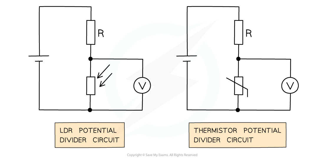
LDR and thermistor in a potential divider circuit with a fixed resistor R
- The voltmeter in both circuits is measuring Vout
- Recall that the resistance of an LDR varies with light intensity
- The higher the light intensity, the lower the resistance and vice versa
- An LDR circuit is often used for street and security lights
- The resistance of a thermistor varies with temperature
- The hotter the thermistor, the lower the resistance and vice versa
- A thermistor circuit is used in fire alarms, ovens and digital thermometers
- From Ohm’s law V = IR, the potential difference Vout from a sensory resistor in a potential divider circuit is proportional to its resistance
- If an LDR or thermistor's resistance decreases, the potential difference through it also decreases
- If an LDR or thermistor's resistance increases, the potential difference through it also increases
- Since the total p.d of the components must be equal to Vin, if the p.d of the sensory resistor decreases then the p.d of the other resistor in the circuit must increase and vice versa
Worked example
A potential divider consists of a fixed resistor R and a thermistor. What happens to the p.d through resistor R and the thermistor when the temperature of the thermistor decreases?
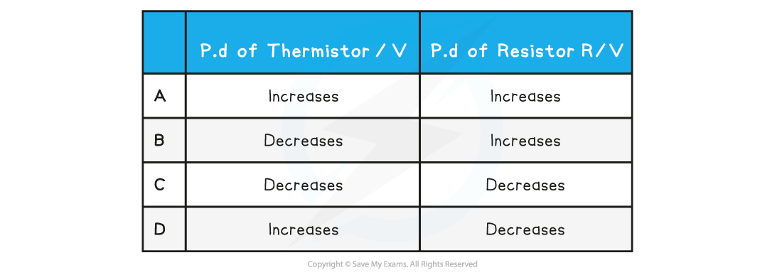
ANSWER: D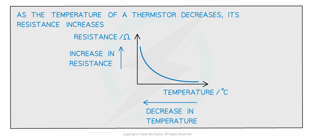
- Due to Ohm’s Law (V = IR), both the resistor and thermistor are connected in series and have the same current I
- If resistance R increases, the potential difference across the thermistor also increases
- In series, the potential difference is shared equally amongst the components. Their sum equals the e.m.f of the supply (Kirchhoff’s second law)
- If the potential difference across the thermistor increases, the potential difference across the resistance R must decreases, to keep the same overall total e.m.f
- This is row D

